Q: What is a heat pump?
A: A heat pump is a piece of air conditioning equipment that has the ability to provide both comfort cooling in the warm summer months as well as comfort heating in the cooler winter months.
Some heat pumps are designed to heat water instead of air. These heat pumps are used in conjunction with spas, pools and hydronic/radiant heating systems.
Q: Can you give me an example of the heat pump concept?
If you think in terms of a window air conditioner you might have in your home, the appliance provides you with cooling during the warm summer months. If you were to walk outside and feel the air coming out from the back of the unit while it is operating, it will be warm. So, we can say that the air conditioner takes heat from inside the structure and moves it to the outside of the structure.
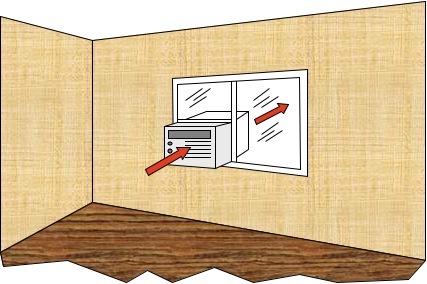
A: An air conditioner moves heat from the inside of a structure to the outside.
So, what would happen if we took the window air conditioner and installed it with the inside portion on the outside and the outside portion on the inside? Well, instead of blowing cold air into the occupied space, we would be blowing warm air. Instead of having hot air blow from the back of the unit, we would be blowing cold air. So, in this case, we would be taking heat from outside and blowing it into the structure.
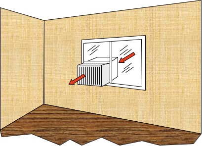
If an air conditioner was turned end-for-end, heat would be transferred from the outside of the structure to the inside.
So, without having to constantly rotate the air conditioner in the window, the heat pump mechanically reverses itself to perform both heating and cooling functions.
Q: How can a heat pump provide both heating and cooling?
A: There are two heat transfer surfaces in a typical heat pump system. One coil or heat transfer surface is located inside the structure, while the other is located outside the structure. These surfaces are referred to as the condenser and the evaporator. The evaporator absorbs heat, while the condenser is responsible for rejecting heat. The function of the heat transfer surfaces can be changed to produce the desired mode of system operation. So, the indoor and outdoor coils can function as either the condenser or the evaporator, depending on the mode it’s operating in.
Q: How does a heat pump system operate in the cooling mode?
A: In the cooling mode, the indoor coil functions as the evaporator and the outdoor coil functions as the condenser. Air from the occupied space passes over the evaporator, or cooling coil, and heat energy is transferred from the air to the coil. This heat is ultimately transferred to the outdoor coil, which is acting as the condenser. At the condenser, the heat is then rejected to the outside.
Q: How does a heat pump system operate in the heating mode?
A: In the heating mode, the indoor coil functions as the condenser and the outdoor coil functions as the evaporator. Air from outside the structure passes over the outdoor coil (the evaporator) and heat is transferred from the air to the coil. This heat is ultimately transferred to the indoor coil, which is acting as the condenser. At the condenser, the heat from outside is transferred to the air passing over the indoor coil.
Q: How does the evaporator absorb heat?
A: In order for the evaporator to absorb heat from a substance, it must be at a temperature that is lower than the medium we are transferring heat from. For example, to cool 75 degree air in an occupied space, the surface temperature of the evaporator must be lower than 75 degrees.
A heat transfer medium, known as a refrigerant, is circulated through the coil to facilitate the desired heat transfer.
Q: How does the condenser reject heat?
A: In order for the condenser to reject heat, the medium that is surrounding the condenser coil must be cooler than the temperature of the condenser coil itself. In other words, the condenser must be maintained at a temperature that is well above the temperature of the surrounding medium.
A heat transfer medium, known as a refrigerant, is circulated through the coil to facilitate the desired heat transfer.
Q: What is a refrigerant?
A: A refrigerant is a chemical substance that has the ability to absorb and reject large amounts of heat energy quickly. By controlling the pressure of the refrigerant at different points in the system, we can determine whether a particular heat transfer surface will operate as the condenser or as the evaporator.
In a heat pump system, refrigerant can be present in any one of three states. These states are 100% liquid, 100% vapor or a mixture of liquid and vapor. When the refrigerant is a mixture of liquid and vapor, the refrigerant is said to be saturated. Saturated refrigerants follow a specific relationship between pressure and temperature. Each refrigerant has its own pressure/temperature relationship.
By utilizing the laws of physics that govern the behavior of saturated refrigerants, we can control the temperature of the refrigerant by controlling its pressure.
Q: What does a pressure/temperature chart look like?
A: Here is a portion of the pressure/temperature chart for R-22, which is a refrigerant commonly found in many heat pump and air conditioning systems.
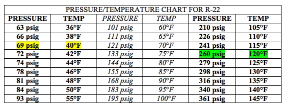
From this chart we can see that saturated R-22 will be at a temperature of 40°F if it is at a pressure of 69 psig. (Refer to the yellow highlighted portion of the chart). We can also see that saturated R-22 will be at a temperature of 120°F if it is at a pressure of 260 psig. (Refer to the green highlighted portion of the chart).
Q: How is the evaporator coil kept cool?
A: The evaporator is the heat exchange surface that absorbs heat into the heat pump system so it must be cooler than the medium being cooled. Since we want the evaporator to be at a low temperature, the pressure of the refrigerant must also be low. We use other system components, namely the compressor and the metering device, to maintain the desired refrigerant pressures in the heat transfer coils.
For cooling applications, when the medium being cooled is the air in the space, a near design evaporator temperature is about 40°F. So, for R-22, the pressure in the evaporator needs to be about 69 psig in order to maintain this temperature. This assumes near design conditions, which are a 75°F indoor air temperature with a relative humidity of 50%, and an outside ambient temperature of 95°F.
For heating applications, the temperature of the evaporator will vary depending on the temperature of the outside air. If the temperature of the outside air is 40°F, then the refrigerant in the evaporator will be at a temperature of about 15°F.
Q: How is the condenser coil kept warm?
A: The condenser is the heat exchange surface that is responsible for rejecting heat from the heat pump system so it must be warmer than the surrounding medium. Because of this, we want the condenser to be at a high temperature. This is accomplished by maintaining the pressure of the refrigerant in the condenser at a high level. We use other system components, namely the compressor and the metering device, to maintain the desired refrigerant pressures in the heat transfer coils.
What are the other system components that make up a heat pump system?
A heat pump system has four major system components. In addition to the evaporator and condenser, the heat pump system also has a compressor and a metering device. These two system components maintain the flow of refrigerant through the heat pump system and also maintain the heat transfer coils at the desired temperatures and pressures.
Q: What does the heat pump compressor do?
A: The compressor is the system component that is responsible for creating a pressure difference in the system that allows refrigerant to flow through the system. It is a vapor pump, so there must be vapor at its inlet as well as vapor at its outlet. The vapor refrigerant that enters the compressor is at a low temperature and a low pressure. At the outlet of the compressor, the vapor refrigerant is at a high temperature and a high pressure. The pressure difference that is created allows the refrigerant to flow from the outlet, or discharge,of the compressor through the heat transfer coils and then back to the inlet of the compressor where the pressure is once again lifted to the desired level. It can be concluded, therefore, that the compressor acts as a dividing point between the high pressure side and the low pressure side of the heat pump system.
Q: What does the metering device do?
A: Like the compressor, the metering device is a system component that acts as a dividing point between the high and low pressure sides of the heat pump system. The metering device acts as a blockage in the refrigerant circuit and restricts flow as the refrigerant flows between the two heat transfer coils. The temperature and pressure of the refrigerant at the inlet of the metering device is high, while the temperature and pressure of the refrigerant at the outlet of the metering device is low.
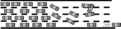
Consider a car accident on a four-lane highway. Traffic builds before the accident, as a number of the travel lanes are blocked. This creates a “high pressure” of sorts before the accident.Now, consider what happens after the point of the collision is passed.The concentration of cars is low and the “pressure” is greatly reduced.
Q: How are all these components connected?
A: The four major system components that were previously discussed make upwhat is called the basic refrigeration cycle. These components are connected to each other as shown in this figure.

Q" How does the system operate?
A: Let’s start at the inlet of the compressor. At the inlet of the compressor,the state of the refrigerant is 100% vapor and is at a low pressure and a low temperature. As the refrigerant flows through the compressor, the refrigerant is compressed and the temperature and pressure of the vapor is increased. At the outlet of the compressor, the refrigerant is at a high temperature and a high pressure. Remember, because the refrigerant is 100% vapor, it does not follow the pressure/temperature relationship for that particular refrigerant.
From the compressor the refrigerant flows to the condenser coil. This is where system heat is rejected. As heat is transferred from the refrigerant to the surrounding medium, the refrigerant begins to condense into a liquid.Now the refrigerant is a mixture of liquid and vapor and it follows the pressure/temperature relationship for that refrigerant.
At the outlet of the condenser, the refrigerant is 100% liquid and then flows onto the metering device. This refrigerant is still at a high pressure and a high temperature. The metering device controls the flow of refrigerant into the evaporator by acting as a blockage. At the outlet of the metering device, the refrigerant is now at a low pressure and a low temperature. The low pressure, low temperature liquid then flows into the evaporator.
The evaporator is the point in the system where heat is introduced to the refrigerant. As heat is added to the refrigerant in the evaporator coil, the refrigerant begins to evaporate or boil. As the liquid refrigerant begins to boil, it once again becomes a saturated refrigerant, or a mixture of liquid and vapor.Since it’s saturated, it follows the pressure/temperature relationship for that refrigerant. At the outlet of the evaporator, the refrigerant is 100% vapor and ready to enter the compressor once again.
Q: How does the heat pump system provide comfort cooling?
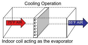
A: When the air in the conditioned space passes over or through the evaporator,heat transfers from the warmer air to the cooler refrigerant that is flowing through the evaporator. At near design conditions, the air passing over the evaporator, or cooling coil, is at a temperature of about 75°F with a relative humidity of about 50%. After passing through the coil, the air temperature is about 55°F.
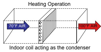
Q: How does the heat pump system provide heating?
A: The heat pump heats the air in the occupied space when the air passes over or through the condenser coil. Since the temperature of the condenser coil is higher than the temperature of the air passing through it, heat is transferred from the warm refrigerant in the condenser coil to the air, thus warming it.
Q: How does the heat pump know when to heat and when to cool?
A: The heat pump system is equipped with a device called the reversing valve.This valve directs the refrigerant to the correct coils at the correct time to provide the desired mode of operation.
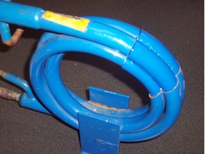
Q: What does the reversing valve look like?
A: Here is a photo of a typical heat pump reversing valve. The valve has the ability to change the direction of refrigerant flow depending on the mode the system is operating in.
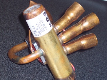
The Reversing Valve
Q: How does the reversing valve operate?
A: The reversing valve is controlled by a solenoid coil that, when energized, causes the valve to change positions.
Q: What exactly is a solenoid?
A: A solenoid is basically a coil of wire. When electric voltage is applied to the coil and current flows through it, a magnetic field is generated. This magnetic field causes the reversing valve to change position. When the solenoid is energized, the system will work in one mode, and in the other mode when the solenoid is d-energized. Depending on the manufacturer of the heat pump equipment, the system mode associated with the energized or de-energized solenoid coil varies.
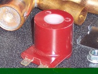
The Solenoid Coil
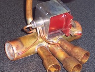
Coil Mounted on the Reversing Valve
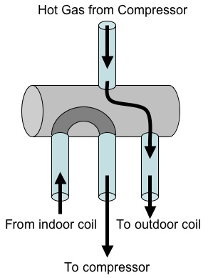
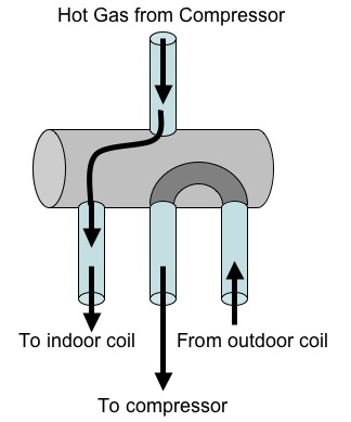
Q: How does the reversing actually redirect refrigerant flow?
A: The reversing valve has four ports:
• One port connected to the outlet of the compressor
• One port connected to the inlet of the compressor
• One port connected to one side of the indoor coil
• One port connected to one side of the outdoor coil
The reversing valve has an internal slide that ultimately determines the mode in which the system will operate.
For example, in the diagram that follows, if the slide is to the left, the refrigerant will flow from the compressor to the outdoor coil. When such is the case, the system is operating in the cooling mode, since the refrigerant always flows to the condenser first upon exiting the compressor. It can also be seen that the “U-bend” directs the refrigerant from the indoor coil, in this case the evaporator, back to the compressor.
When the system operates in the heating mode, the indoor coils acts as the condenser. In this case, the hot gas from the compressor is directed to the indoor coil, which is functioning as the condenser. It can be seen that the refrigerant from the outdoor coil, in this case the evaporator, is directed back to the compressor via the “U-bend” in the reversing valve.
You should be able to note that, in the following two photos, the direction of refrigerant flow through the tube on the left side of the valve remains the same, even though the slide has changed position. The same can be said for the center pipe connection on the right side of the valve. As the slide position changes, the direction of refrigerant flow changes only in the top and bottom pipes of the right hand side of the valve.
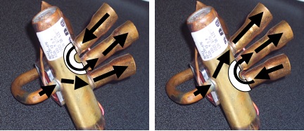
The two positions of the reversing valve.
Q: Where is the reversing valve located in the heat pump system?
A: The reversing valve is typically located between the compressor outlet (discharge) and the inlet of the outdoor coil. If the system is a split-type system, this location is within the outdoor portion of the system.
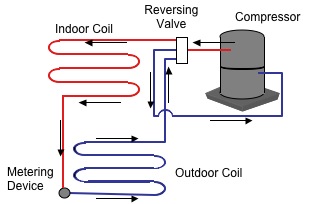
Q: How does the refrigerant flow through the system in the heating mode?
A: The refrigerant (upon leaving the compressor via the red line in the following diagram) first flows through the reversing valve where it is directed to the indoor coil. Since the refrigerant always flows to the condenser first after leaving the compressor, the indoor coil is acting as the condenser. In this mode of operation, the heat from the refrigerant is rejected to the air in the occupied space. From the indoor coil, the refrigerant flows through the metering device and then to the outdoor coil, where the refrigerant picks up or absorbs heat from the outside air. The refrigerant then flows back to the compressor via the reversing valve and the cycle repeats itself.
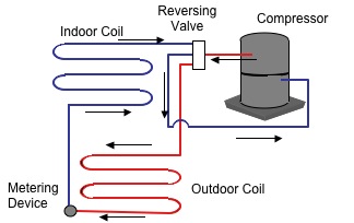
Q: How does the refrigerant flow through the system in the cooling mode?
A: The refrigerant (upon leaving the compressor via the red line in the following diagram) first flows through the reversing valve where it is directed to the outdoor coil. Since the refrigerant always flows to the condenser first after leaving the compressor, the outdoor coil is acting as the condenser. In this mode of operation, the heat from the refrigerant is rejected to the outside air. From the outdoor coil, the refrigerant flows through the metering device and then to the indoor coil, where the refrigerant picks up or absorbs heat from the air in the area being cooled. The refrigerant then flows back to the compressor via the reversing valve and the cycle repeats itself.
Q: Do all heat pump systems have reversing valves?
A: No. Heat pumps that are intended to provide both heating and cooling are equipped with reversing valves. However, heat pump systems that are intended to provide only heating are not equipped with reversing valves.
Q: Can you give me an example of a heat pump system that does not have a reversing valve?
A: The heat pump swimming pool heater does not use a reversing valve. The sole purpose of the heat pump pool heater is to heat the water in the swimming pool. This heat pump is never used to cool the pool water, so there is no need for the system to operate in both the heating and cooling mode. The heat pump swimming pool heater is an air-to-water heat pump and uses one air-to-refrigerant heat exchanger and one refrigerant-to-water heat exchanger.
The hot gas from the compressor is piped directly to the tube-in-tube heat exchanger and transfers heat to the pool water. The refrigerant leaves this heat exchanger as a high temperature, high pressure liquid and, after flowing through the metering device, flows to the outdoor coil as a low temperature, low pressure liquid. It is at the outdoor coil, the evaporator, that heat from the outdoor air is transferred to the refrigerant.
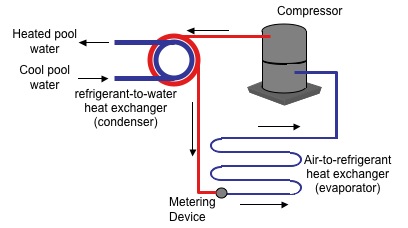
Simplified piping diagram of a heat pump swimming pool heater.
Q: Are all heat pump systems the same?
A: Definitely not! There are many different types of heat pumps and are classified by the jobs they are to do as well as how they are designed to do these jobs. For example, heat pumps can be used to heat or cool water, air or other fluids.
For heat pumps to heat a substance, there must be a source of this heat, or heat source. This heat source can be water, air, or even the Earth. When water is used, it can come from a cooling tower or it can come from an underground well. When we use the Earth as a heat source, the heat of the Earth itself is used as a heat source when the system is operating in the heating mode and as the heat sink when the system is operating in the cooling mode.
Q: What is a Geothermal Heat Pump?
A: The term geothermal is made up of two parts. The first portion of the word is “geo” and refers to the Earth and is the root of words such as geography, meaning the study of the Earth, and geology, which is the study of the origin, history and structure of the Earth., The rest of the word is “thermal”, which is related to the production, use, study or transfer of heat. So, getting away from the good old American Heritage College Dictionary, we can quickly conclude that the term geothermal refers to the heat that is contained in the Earth.
When we use the term geothermal heat pump, we are referring to heat pump systems that utilize the Earth as both a heat source and a heat sink depending on the mode in which the heat pump is operating. Geothermal heat pumps can use either the heat in the Earth/soil itself or it can use the water that is located underneath the Earth’s surface.
Q: How are heat pumps classified?
A: Heat pumps are classified based on the fluid used for the heat source while the heat pump is operating in the heating mode. For example, a heat pump that uses air as its heat source when operating in the heating mode is referred to as an air-source heat pump. Also, a heat pumps system that uses water as its heat source when operating in the heating mode is classified as a water-source heat pump.
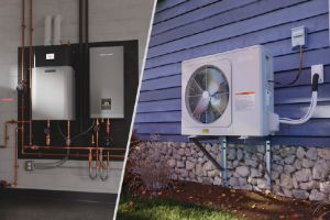
Q: Can you give me some examples of an air source heat pump?
A: As just mentioned, air source heat pumps use air as the heat source when the system is operating in the heating mode. An other important thing to consider is the fluid that is ultimately being treated. For example, we can use the heat in the air to heat air, or water. When we use the heat in the air to heat air, we call that heat pump an air-to-air heat pump. When we use the heat in the air to heat water, we call that heat pump an air-to-water heat pump. The first part of the classification refers to the source of heat when the system is operating in the heating mode and the second part of the classification refers to the medium that is being treated. So, in general terms, a heat pump that is classified as X-to-Y uses the heat in “X” to ultimately heat “Y”.
An example of an air-to-air heat pump is a typical unit used for comfort cooling and heating. We use the heat contained in the outdoor air to heat the air inside the occupied space.
An example of an air-to-water heat pump would be a radiant heating system. In this case, the heat from the outside air is used to heat water that is ultimately circulated through the radiant heating system. Another example of an air-to-water heat pump system would be a pool heater. In this case, heat from the outside air is used to heat the water in a swimming pool.
Q: Can you give me some examples of a water source heat pump?
A: Water source heat pumps use water as the heat source when the system is operating in the heating mode. An other important thing to consider is the fluid that is ultimately being treated. For example, we can use heat in the water to heat air, or water. When we use heat in water to heat air, we call that heat pump a water-to-air heat pump. When we use the heat in water to heat water, we call that heat pump an water-to-water heat pump. The first part of the classification refers to the source of heat when the system is operating in the heating mode and the second part of the classification refers to the medium that is being treated. So, in general terms, a heat pump that is classified as X-to-Y uses the heat in “X” to ultimately heat “Y”.
Water-to-air heat pumps are used for comfort heating and cooling. We use the heat in the water to provide for the heating of the occupied space.
Water-to-water heat pumps can be used in a variety of applications including radiant heating systems and pool/spa heating.
Q: Where does the water supply come from for water-source heat pumps?
A: In most cases, the water that is used in conjunction with residential water-source heat pumps comes from wells. These wells are drilled on the property and must be deep enough to reach the water table. Commercial applications utilize a cooling tower to provide the water needed for proper system operation. Another popular heat pump configuration utilizes buries loops of piping that contain either water or a water/antifreeze mixture. Heat pump systems that utilize wells or cooling towers are referred to as open-loop systems while those that utilize buried, water-filled loops are referred to as closed-loop systems.
Q: What is an open-loop heat pump system?
A: An open loop heat pump system is one that utilizes a water source that is open to the atmosphere or Earth. We can also say that open loop heat pump systems have, for the most part, “uncontained” water sources. During the heating mode, heat is transferred from the water in the Earth to the refrigerant circuit. This heat is then transferred from the refrigerant circuit to the air or water that is being heated. Open loop heat pump systems rely on a constant supply of underground water, so this must be taken into account before the decision is made about which type of loop system will be used. In addition, the mineral concentration in the water can affect system operation so this, too, must be evaluated by a profession trained to evaluate the quality of the water in a particular geographic region.
Q: What is a closed-loop heat pump system?
A: A closed loop system utilizes loops or coils of buried tubing that contain water or a water/antifreeze mixture. These loops are sealed and, if there are no leaks, will remain completely filled all the time. The water contained in these loops is used over and over to facilitate the transfer of heat either into or out of the heat pump system. The closed loop system is a popular choice when the water table is far below the ground, the ground water temperature is too low, the water quality is poor or the mineral content is too high. Closed loop systems often require much more installation-related damage to the property as the loops that are buried are quite large and can, depending on the selected configuration, cover a large are of the property.
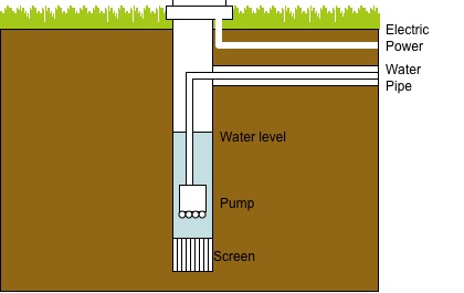
Q: What does a well look like?
A: From the top, the typical well does not look like much. Probably the only thing you will see is the well cap, which is the only part of the well that is above ground. Underground, however, there is a lot more going on. The well must be drilled deep enough to allow the pump to be positioned below the static water line, or water table. There is a screen at the bottom of the well that prevents foreign matter from entering the well and the pump. There is a water line, often referred to as a drop pip, that connects the pump outlet to the underground water line. The underground water line carries the water from the well to the heat pump system.
Q: What is a Water Table?
A: The water table is the point or level where underground water is found. The exact location of the water table varies with geographic location, so experienced well-drillers are consulted to determine how deep a particular well must be drilled. This will help ensure that ample water will be available for the system. During periods of excessively dry weather, the water table can drop and, during periods of excessive rainfall, the water table can rise. Although a rising water table will not have a negative effect on heat pump system operation, a falling water table can dramatically reduce the amount of water available to the system and may, in severe instances, prevent the system from operating.
Q: Why can’t we use domestic water in a water-source heat pump?
A: Large amounts of water are required to flow through water-source heat pumps in order to provide the needed capacity. For the most part, using the local municipal water supply for heat pump operations is illegal. Be sure to check the laws in your area before attempting to use your tap water supply for your heat pump.
Q: How do wells provide water for the heat pump system?
A: Pumps are positioned at the bottom of the well to supply the needed water to the system. When the system is in operation and water is needed, the pump will turn on and pump water from the well to the water-refrigerant heat exchanger in the heat pump system.
Q: Does the pump have to run whenever the system is operating?
A: Sometimes. If the system is not using a pressure tank, the answer is yes. This means that the pump will cycle on and off with the heat pump and can, in the event of system short-cycling, lead to premature pump failure. If the system utilizes a pressure tank, the pump’s run cycles will be less frequent.
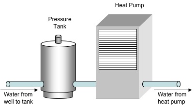
Q: What exactly is a pressure tank?
A: A pressure tank is a tank that stores pressurized water until it is needed by the heat pump system. The pressure in the tank is maintained at a desired level. When the tank pressure is low, the pump is cycled on and water is pumped into the tank. Once the tank pressure reaches the desired level, the pump is cycled off. As the heat pump system operates, water is fed from the pressure tank and through the heat pump. When the pressure in the tank drops below a predetermined level, the pump is cycled on again to increase the water pressure in the tank. The pressure tank is located between the supply well and the heat pump.
Q: Are there different well configurations and setups?
A: Yes. Water-source heat pumps can be configured with a number of different well configurations. Heat pump systems can utilize a supply well and a return well, a one-well system, a supply well and a dry well or a dedicated geothermal well. The type of well system used is determined, in part, by the geographic location of the system.
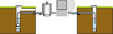
Q: How is a two-well (supply and return) system configured?
A: The two-well system utilizes one well to supply the water to the heat pump system and another well to receive the water that has already flowed through the heat pump. The configuration is shown in the following diagram. The supply well feeds water to the pressure tank, which feeds water to the heat pump. Once the water has passed through the heat exchanger in the heat pump, the water is then sent back to the ground via the return well. The wells should be at least 100 feet from each other to prevent the heat from the water in the return well from affecting the operation of the system. Here's a drawing of a two-well system.
Q: How is a one well system configured?
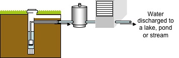
A: If the system is located near a pond, river or lake, the water that is discharged by the heat pump system can be directed to it. In this configuration, the water is brought to the system by the well and then discharged directly to the pond, river or lake. Since the water does not come in contact with any chemicals or other substances within the system, no environmental damage results. It is important, though, to check with local codes and guidelines relating to the installation of this type of heat pump system. A one-well system utilizes a lake, pond or stream to accept the water discharged from the system.
Q? How is a supply well/dry well system configured?
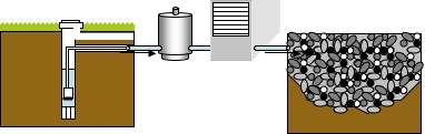
A: If the ground is comprised of sandy soil, the dry well configuration may be used. A dry well is little more than a large hole filled with a combination of gravel and/or sand. The line that carries the water from the heat pump is directed to the dry well. The water seeps through the gravel-filled well and returns to the ground. A dry well is used to accept the water that is discharged from the heat pump system. Like this:
Q: How is a dedicated geothermal well system configured?
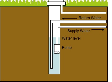
A: A dedicated geothermal well is a one-well system that provides for both the supply of water to the heat pump as well as the for the return of water leaving the heat pump system. The geothermal well has both supply water and return water piping connections. The water that is returning to the well from the heat pump is introduced to the well approximately three to four feet below the point where water is pumped from the well to the heat pump system. A cutaway of a dedicated geothermal well is shown here.
Q: How is heat transferred from the water in the Earth to the heat pump system?
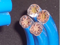
A: The water in Earth and the refrigerant in the heat pump system pass through a tube-in-tube heat exchanger such as this one. The tube-in-tube heat exchanger is configured as a tube positioned within another tube. The water flows through the inner tube while the refrigerant flows through the outer tube.
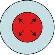
In the heating mode, heat is transferred from the water to the refrigerant, causing the refrigerant to boil to a vapor at low temperatures. In the cooling mode, heat from the hot vapor refrigerant is transferred to the water, rejecting heat from the system and allowing the refrigerant to condense into a liquid. In the following two diagrams, the outer circle represents the refrigerant path while the inner circle represents the water path. The light blue indicates the lower temperature fluid and the red represents the higher temperature fluid. In the cooling mode, the high temperature refrigerant transfers heat to the cooler water, which is then transferred back to the Earth.
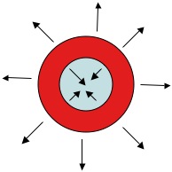
In the heating mode, the higher temperature water transfers heat to the cooler refrigerant, which is then transferred to the medium being heated.
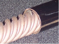
Here's a cutaway of an actual tube-in-tube heat exchanger. Notice how the inner tube is not smooth, but grooved to allow for greater heat transfer.
Q: If the heat pump is being used to heat and cool air, how does the heat from the heat pump get to the air?
A: Just like any other air conditioning unit, there is a fin and tube coil through which the refrigerant flows. When the heat pump is operating in the heating mode, the hot gas from the compressor is routed to the indoor coil. A blower then passes air from the conditioned space through the coil and heat is transferred from the refrigerant to the air. When the heat pump is operating in the cooling mode, the refrigerant that flows through the indoor coil is a low temperature liquid. As the blower passes air from the conditioned space through the coil, the air, being warmer than the refrigerant, transfers heat to the refrigerant, thereby cooling the air.
Q: If the heat pump is being used to heat water, how does the heat from the heat pump get to the water?
A: Instead of using a fin and tube heat exchanger that was used to transfer heat to air, another tube-in-tube heat exchanger is used. This type of system will use on tube-in-tube heat exchanger to transfer heat between the Earth water and the heat pump and another to transfer heat from the refrigerant in the heat pump to the water being used for heating purposes.
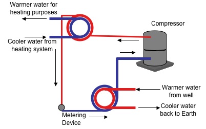
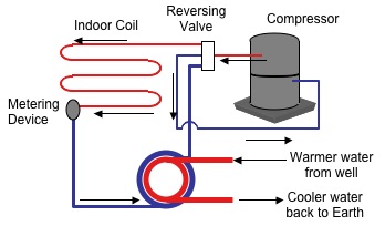
Q: What would the piping diagram look like for a water to air heat pump?
A: A water-to-air heat pump uses water as the heat source to ultimately heat air. Since we are heating air, the indoor coil is of the fin-and-tube variety. Also, since the source of the heat is water, the water-to-refrigerant heat transfer surface will be of the tune-in-tube variety. Here is a simplified piping diagram of this type of system.
Q: What would the piping diagram look like for a water to water heat pump?
A: A water-to-water heat pump uses water as the heat source to ultimately heat water. Since we are heating water with water, both heat exchangers will be of the tube-in-tube variety. Here is a simplified piping diagram of this type of system.